Have you ever meticulously wired a DIY electronics project, only to find it stubbornly refuses to power on or, worse, emits a puff of smoke? The culprit is often a simple yet critical oversight: incorrect polarity. For any electronics enthusiast, understanding and knowing how to identify positive and negative pads is a fundamental skill that can save your components, your sanity, and even prevent potential hazards. In the exciting world of DIY, where every connection counts, mastering polarity ensures your creations come to life exactly as intended. This comprehensive guide will equip you with the knowledge and practical techniques to confidently identify positive and negative terminals, ensuring your projects run smoothly and safely.
Understanding Polarity: Fundamentals and Importance in DIY
At its core, polarity in electronics refers to the direction of electric current flow in a direct current (DC) circuit. Every DC power source and polarized component has a positive terminal (anode), representing a higher electrical potential, and a negative terminal (cathode), representing a lower electrical potential. Electrons, the charge carriers, flow from the negative to the positive terminal. This directional flow is crucial because many electronic components are designed to function correctly only when current passes through them in a specific direction.
Why does correctly identifying positive and negative pads matter so profoundly in your DIY endeavors? Firstly, for component functionality, many parts like diodes, Light Emitting Diodes (LEDs), and electrolytic capacitors are unidirectional devices. Connect them in reverse, and they simply won’t work, or they might suffer irreversible damage [2 (Why Polarity), 1 (Kasuo)]. Secondly, circuit integrity relies on precise current flow; incorrect polarity can disrupt the entire circuit’s intended operation, leading to unpredictable behavior or complete failure [2 (Why Polarity), 1 (PCBMade)]. Most importantly, safety is paramount. Reverse polarity, especially with power supplies or batteries, can cause components to overheat, short-circuit, emit smoke, or even explode, posing risks of fire or personal injury [2 (Why Polarity), 1 (PCBMade)]. While alternating current (AC) does not have a fixed polarity, DC circuits demand strict adherence to positive and negative connections for successful and safe operation.
Essential Tools and Visual Cues for Polarity Identification
Accurately identifying polarity often begins with keen observation and, for more certainty, the right tools. Here are the primary methods DIYers use to determine positive and negative pads:
Visual Inspection: Markings, Colors, and Shapes
The easiest and often first step is to look for visual indicators directly on the component or wiring.
- Symbols and Color Codes: Batteries and many power supplies clearly mark their terminals with a “+” for positive and a “–” for negative. In wiring, red wires typically denote positive (+), while black wires are used for negative (–) or ground [1 (FridayParts), 2 (How to Identify Terminals)]. This color coding is a universal convention, especially in DC applications.
- Lead Length: For many new through-hole components like LEDs and electrolytic capacitors, the positive lead (anode) is noticeably longer than the negative lead (cathode) [1 (Kasuo), 2 (Instructables), 1 (LED Polarity)]. This simple cue can be a quick indicator, though it’s less reliable for salvaged components or those with trimmed leads.
- Component Body Markings:
- Diodes and LEDs: Many diodes feature a band or stripe on one end of their cylindrical body. This stripe consistently marks the cathode, or negative terminal [1 (Kasuo), 4 (Diode Polarity)]. For LEDs, in addition to lead length, you might find a flattened edge on the plastic housing, which corresponds to the cathode side [2 (LED Polarity), 1 (LED Polarity)]. Some also have a larger internal metal plate connected to the negative lead and a smaller one to the positive [2 (LED Polarity)].
- Electrolytic Capacitors: These often have a stripe running down one side of their body, typically accompanied by minus signs (“-“). This stripe unequivocally indicates the negative terminal [4 (Common Parts)].
- Integrated Circuits (ICs): While ICs don’t have a simple positive/negative polarity for their entire body, identifying pin 1 is crucial for correct orientation. Pin 1 is often indicated by a small dot, a notch, or a chamfered corner on the chip’s package [4 (Common Parts), 3 (Component Polarity)].
|
Our Picks for the Best LED strip light in 2026
As an Amazon Associate I earn from qualifying purchases.
|
||
| Num | Product | Action |
|---|---|---|
| 1 | Govee RGBIC LED Strip Lights, Smart LED Lights for Bedroom, Bluetooth LED Lights APP Control, DIY Multiple Colors on One Line, Color Changing LED Strip Lighting Music Sync, Home Decor, 16.4ft |

|
| 2 | White Led Strip Lights for Bedroom Small Dimmable LED Lights Strip 16.4ft Super Bright Flexible LED Tape Lights Rope Light for for Room Home Decor Luces Leds for Living Room Kitchen Vanity Mirror |
|
| 3 | DAYBETTER LED Strip Lights 110ft, Smart Lighting Strips with App Remote Control, RGB Music Sync Color Changing Lights for Bedroom Kitchen Party Home Decor Luces led para cuarto (1 Roll) |
|
| 4 | dalattin White LED Strip Lights, 20ft Dimmable Super Bright 24V Led Tape Light 6500K 360 LEDs Lights for Bedrooms, Mirror, Kitchen, Home Decoration Daylight White |
|
| 5 | Govee 100ft RGBIC LED Strip Lights, Smart LED Lights Work with Alexa and Google Assistant, LED Lights for Bedroom WiFi App Control Segmented DIY Multiple Colors, Color Changing Light, (2 x 50ft) |
|
| 6 | KSIPZE 100ft Led Strip Lights RGB Music Sync Color Changing Led Lights with Smart App Control Remote Led Lights for Bedroom Room Lighting Flexible Home Décor |
|
| 7 | Govee White LED Strip Lights, Upgraded 16.4ft Dimmable LED Light Strip 6500K Bright Daylight White, Strong Adhesive, 300 LEDs Flexible Tape Lights for Mirror, Kitchen Cabinet, Bedroom, Christmas Decor |
|
| 8 | DAYBETTER Led Strip Lights 32.8ft Kit with Remote and Power Supply Color Changing |
|
| 9 | NBBUFF Led Lights for Bedroom 50ft (1 Roll), Color Changing RGB Led Strip Lights with 60 Keys Remote and App Control, Music Sync Led Lights for Room Kitchen Party Home Decor |
|
| 10 | Barrina (6 Pack LED T5 Integrated Single Fixture, 4FT, 2200lm, 6500K Super Bright White, 20W Utility LED Shop Light, Ceiling and Under Cabinet Light, Corded Electric with ON/Off Switch, ETL Listed |
|
Multimeter Usage: The DIYer’s Best Friend
When visual cues are ambiguous or absent, a digital multimeter (DMM) is an indispensable tool for accurate polarity identification.
- DC Voltage Measurement:
- Set your multimeter to measure DC voltage (often denoted by
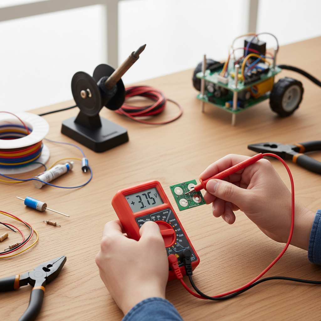
V--orVDC). - Connect the red probe to the multimeter’s “VΩmA” jack (positive) and the black probe to the “COM” jack (negative).
- Touch the red probe to one terminal of the component or power source and the black probe to the other.
- Observe the reading on the display. If the voltage displayed is a positive value, it means your red probe is currently connected to the positive terminal, and the black probe to the negative. If the display shows a negative value (e.g., -5V), it indicates that your probes are reversed relative to the component’s polarity – the red probe is on the negative terminal, and the black is on the positive [1 (Multimeter), 2 (Multimeter), 5 (Multimeter)].
- Set your multimeter to measure DC voltage (often denoted by
- Diode Test Mode (for LEDs and Diodes): Many multimeters have a dedicated diode test mode.
- Switch your multimeter to this mode (often indicated by a diode symbol).
- Connect the red probe to the component’s presumed anode (positive) and the black probe to the presumed cathode (negative).
- If correctly connected, a diode will typically show a voltage drop (e.g., 0.6V for a silicon diode) or, in the case of an LED, it may light up faintly [1 (LED Polarity)]. If connected in reverse, the multimeter will usually display “OL” (Open Loop) or “1”, indicating infinite resistance.
Component-Specific Polarity Identification Guides
Understanding general methods is helpful, but specific components have their own unique characteristics for polarity identification.
- Batteries: Always look for the “+” and “–” symbols clearly marked on the battery casing [1 (FridayParts), 2 (How to Identify Terminals)]. For larger batteries like car batteries, the positive terminal is often slightly larger in diameter. Red cables are almost universally positive, and black cables are negative.
- LEDs (Light Emitting Diodes): For new LEDs, the longer lead is the anode (positive), and the shorter lead is the cathode (negative) [1 (Kasuo), 2 (Instructables), 1 (LED Polarity)]. Additionally, examine the LED’s plastic casing: there’s often a flat edge on the cathode side [2 (LED Polarity), 1 (LED Polarity)]. Inside the LED, the smaller metal plate is connected to the anode, and the larger, flag-shaped plate is connected to the cathode [2 (LED Polarity), 4 (LED Polarity)]. When using a multimeter in diode test mode, the LED will light up if the red probe is on the anode and the black on the cathode [1 (LED Polarity)].
- Diodes (Rectifier, Zener, etc.): The cathode (negative) of a diode is almost always marked with a band, stripe, or ring on its body [1 (Kasuo), 4 (Diode Polarity)]. The unmarked side is the anode (positive). This marking convention is crucial for correct installation, as diodes block current flow in the reverse direction.
- Electrolytic Capacitors: These polarized capacitors are vital in many circuits for smoothing voltage. Their negative terminal is identified by a stripe running along the side of the capacitor body, typically containing minus (“-“) symbols [1 (Kasuo), 4 (Common Parts)]. For through-hole versions, the longer lead is positive, and the shorter lead is negative when new [1 (Kasuo)]. Unlike electrolytic capacitors, most ceramic and film capacitors are non-polarized and can be installed in either orientation without issue [4 (Common Parts), 5 (Jotrin)]. Always check the datasheet if unsure, especially for tantalums which are inherently polarized [5 (Jotrin)].
- Integrated Circuits (ICs): ICs are complex components where precise orientation is critical rather than simple positive/negative terminals for the whole chip. Pin 1, which serves as a reference point for all other pins, is indicated by a notch or a small dot on the chip’s body [4 (Common Parts), 3 (Component Polarity)]. This aligns with a corresponding marking on the Printed Circuit Board (PCB).
| Component/Method | Positive Indication | Negative Indication | Notes |
|---|---|---|---|
| General Wiring | Red Wire, “+” symbol | Black Wire, “-” symbol | Standard color coding in DC circuits |
| Batteries | “+” symbol, larger terminal | “-” symbol, smaller terminal | Visibly marked on casing and posts |
| LEDs (new) | Longer Lead, Smaller Internal Plate, “+” symbol (rare) | Shorter Lead, Larger Internal Plate, Flat Edge on Casing, “-” symbol (rare) | Visual cues are common and often multiple |
| Diodes | Unmarked side (Anode) | Band/Stripe on body (Cathode) | Stripe is the key identifier for unidirectional flow |
| Electrolytic Caps | Longer Lead (new) | Stripe with “–” signs, Shorter Lead (new) | Crucial for function, reversed connection can lead to failure |
| Multimeter (DCV) | Positive Voltage Reading (Red probe on positive terminal) | Negative Voltage Reading (Red probe on negative terminal) | The most reliable diagnostic tool |
Troubleshooting Common Polarity Mistakes and Ensuring Safety
Even experienced DIYers can make polarity mistakes. Recognizing common errors and adhering to safety protocols can prevent costly damage and ensure your well-being.
Common Mistakes and Their Consequences
One frequent error is reversing battery connections, which can instantly damage sensitive electronics like microcontrollers or integrated circuits [2 (Why Polarity), 1 (FridayParts)]. For LEDs and diodes, incorrect orientation simply means they won’t light up or allow current to pass, but prolonged reverse voltage can still degrade or destroy them. With electrolytic capacitors, reversed polarity is particularly dangerous; it can cause the capacitor to overheat, swell, leak electrolyte, and even violently explode [2 (Instructables), 2 (Why Polarity)]. These catastrophic failures highlight why careful attention to polarity is paramount. Beyond component damage, reversed polarity can lead to circuit malfunction, causing unexpected behavior or complete operational failure [2 (Why Polarity)].
“Ignoring polarity isn’t just about whether your project works; it’s about protecting your components and, most importantly, yourself. A multimeter is your shield against silent component killers.” – John Smith, Senior Electronics Technician
Ensuring Safety and Best Practices
To avoid common pitfalls and ensure safety in your DIY projects, always follow these best practices:
- Double-Check Everything: Before applying power, visually inspect all polarized components. Cross-reference markings with datasheets or diagrams if available.
- Use a Multimeter: Make it a habit to confirm polarity with a multimeter, especially for power sources and unfamiliar components. This is the most reliable method.
- Disconnect Power: Always disconnect the power source before making or changing any connections. Working on a live circuit is extremely dangerous.
- Low-Voltage Tests: When testing sensitive components like LEDs, start with a low-voltage power source (e.g., a coin cell battery for LEDs) to confirm polarity before integrating them into higher-power circuits.
- Solder Carefully: When soldering, ensure that components are oriented correctly on the PCB. Many PCBs have silkscreen markings indicating polarity.
- Understand Component Limits: Be aware that some components, like certain types of diodes or LEDs, have a maximum reverse voltage rating beyond which they can be damaged even if not conducting.
Conclusion
Mastering how to identify positive and negative pads is an indispensable skill for anyone venturing into DIY electronics. From basic battery connections to complex circuit integrations, accurate polarity ensures functionality, longevity, and safety for your projects and components. By understanding visual cues, utilizing a multimeter effectively, and adhering to best practices, you empower yourself to build with confidence and precision. Embrace these techniques, and you’ll navigate the world of electronics with greater success, turning your creative visions into working realities.
What challenging polarity puzzles have you solved in your DIY journey, and what tips did you find most useful?
Frequently Asked Questions
What happens if I reverse polarity on an LED?
If you reverse polarity on an LED, it generally will not light up because diodes (including LEDs) only allow current to flow in one direction. While simply not working is the most common outcome, prolonged reverse voltage can degrade or permanently damage the LED, especially if the reverse voltage exceeds its maximum rating.
Are all capacitors polarized?
No, not all capacitors are polarized. Electrolytic capacitors (aluminum, tantalum) are polarized and must be connected with correct polarity, indicated by markings on their body and lead length. However, ceramic, film, and non-polar electrolytic capacitors are unpolarized and can be installed in either direction. Always check component specifications or datasheets if unsure.
Can I use a multimeter to check AC polarity?
No, a multimeter cannot be used to check AC polarity in the same way it checks DC. Alternating Current (AC) continuously reverses direction, meaning it doesn’t have fixed positive and negative terminals. While a multimeter can measure AC voltage, it won’t indicate a constant positive or negative pole because the voltage is constantly oscillating.
How can I identify polarity if a component has no markings?
If a component has no discernible markings, a multimeter is your best bet. For components like diodes or LEDs, use the diode test mode. For other devices or power sources, use the DC voltage mode; a positive reading indicates the red probe is on the positive terminal, while a negative reading means the probes are reversed.
Is lead length always reliable for LED polarity?
For brand-new, standard through-hole LEDs, the longer lead almost always indicates the positive (anode) terminal. However, this method is not reliable for salvaged LEDs, surface-mount devices (SMDs), or if the leads have been trimmed. In such cases, using a multimeter’s diode test mode or looking for a flat edge on the casing provides more certainty.
What is the difference between anode and cathode?
In electronics, the anode is the positive terminal or electrode where current conventionally flows into a device. Conversely, the cathode is the negative terminal or electrode from which current conventionally flows out of a device. For components like diodes and LEDs, current flows from the anode to the cathode when forward biased.